Full code checking can be performed on standard cold formed steel shapes, based on the following codes:
Note:
Cold formed shape properties are available in the database and the values are based on the AISI or manufacturer values, whichever is selected (See Cold Formed Steel Database). You may also input your own basic shapes and the properties will be calculated automatically.
The Cold Formed tab on the Beams Spreadsheet
![]()
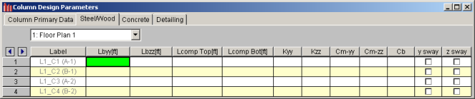
These parameters are defined for each cold formed member. The entries are explained below. The pull down list at the top of the spreadsheet allows you to toggle between floors.
You may assign a unique Label to all of the members. Each label
must be unique, so if you try to enter the same label more than once you
will get an error message.
The
See the Unbraced Lengths topic.
See the Unbraced Lengths topic.
See the Unbraced Lengths topic.
Cm Coefficients are described in Section C5 of the AISI code. If
these entries are left blank, they will be automatically calculated.
The Cm value is influenced by the sway condition of the member and is dependent on the member's end moments, which will change from one load combination to the next, so it may be a good idea to leave these entries blank.
Note
For the cold formed codes, Cb Coefficients are used in the calculation of the nominal
flexural strength, Mn. If
this entry is left blank, it will be calculated automatically.
The R Value for cold formed steel design is described in Section I6.2.1 of the AISI code and is used to calculate the moment capacity of beams that have one flange fastened to deck or sheathing. This value only applies to C or Z members and can vary from 0.4 to 0.7 based on the depth of the member (See Table I6.2.1-1 in the AISI Supplement for the actual values).
If a value is entered by the user, that value will be used by the program in the moment capacity calculation of the member. There are a number of restrictions that must be met to use this section of the code for moment capacity and the user is responsible to check that these restrictions are satisfied.
Note:
The Design Results Spreadsheet displays the optimized design results for the beam elements and may be accessed by selecting Designs on the Results menu. The spreadsheet has six tabs: Hot Rolled, Cold Formed, Wood, Steel Products, Wood Products, and Concrete. The pull down list at the top of the spreadsheet allows you to toggle between floors.
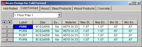
The Label column lists the beam label.
The Size column displays the beam size. When no adequate member could be found from the available shapes list, this field will display the text “not designed”. Consider re-framing, relaxing the design or deflection requirements (see Design Optimization), or adding more shapes to the available Redesign List (see Appendix A – Redesign Lists).
The Explicit column displays "Yes" if the beam has been locked to an explicit beam size by the user. When you have chosen a specific shape to override the programs automatic redesign, that beam becomes "locked" and will not be automatically redesigned by the program.
Note
The Material Column displays the material label assigned to the beam.
The Max Start & End Reactions column displays the maximum start and end reactions of the beam for ALL load combinations. If "Show Factored End Reactions" in Model Settings is left unchecked, these displayed forces are not factored. If it is checked, then the displayed forces will have been multiplied by the factors in the load combinations. The sign convention assigns positive reactions to downward forces. Negative reactions, if they occur, would indicate uplift.
The Min Start & End Reactions column displays the minimum start and end reaction of the beam.
The Code Checks Spreadsheet summarizes the code check results for the beams and may be accessed by selecting Code Checks on the Results menu. The spreadsheet has five tabs: Hot Rolled, Cold Formed, Wood, Concrete, and Wood Products. The pull down list at the top of the spreadsheet allows you to toggle between floors.
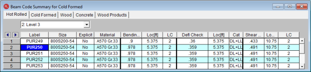
The Label column displays the beam label.
The Size column displays the beam size. When no adequate member could be found from the available shapes, this field will display the text "not designed". Consider re-framing, relaxing the design or deflection requirements (see Design Optimization), or adding more shapes to the available Redesign List (see Appendix A – Redesign Lists).
The Explicit column displays "Yes" if the beam has been locked to an explicit beam size by the user. When you have chosen a specific shape to override the programs automatic redesign, that beam becomes "locked" and will not be automatically redesigned by the program.
Note
The Material Column displays the material label assigned to the beam.
The Bending Check and Shear Check columns display the maximum bending check and shear check calculated by the program. This value is equal to the actual bending or shear demand (stress or force) divided by the actually beam resistance (allowable stress or ultimate capacity). You can see the details of these values in the Bending Results or Shear Results spreadsheet. This check is calculated at 100 stations along each beam for each load combination and the maximum check is reported.
Note
The Deflection Check displays the maximum deflection check. This value is equal to the ratio of actual deflection to allowable deflection. You can see the details of these values in the Deflection Results spreadsheet. This check is calculated at 100 stations along each beam and the maximum check is reported. See Beam Results - Deflection for more information.
The Location columns display the location along the member where the maximum bending, shear, or deflection check occurs.
The LC column displays the controlling load combination which resulted in the maximum bending or shear check.
Deflection checks are based on Load Categories (Dead, Live or DL+LL), not Load Combinations. Therefore, the controlling load Category for deflections is reported in the Cat column.
The Shear Results Spreadsheet records the shear results for the beam elements and may be accessed by selecting Shear on the Results menu. The spreadsheet has four tabs: Hot Rolled, Cold Formed, Wood, and Concrete. The pull down list at the top of the spreadsheet allows you to toggle between floors.
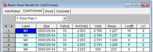
The Label column displays the beam label.
The Size column displays the beam size. When no adequate member could be found from the available shapes, this field will display the text “not designed”. When this occurs, consider re-framing, relaxing the design or deflection requirements (see Design Optimization), or adding more shapes to the available Redesign List (see Appendix A – Redesign Lists).
The Fy column displays the yield strength of the material.
Note:
The Vn/Om or phi*Vn column displays the calculated allowable shear capacity based on Section C3 of the applicable AISI code. The Vu column displays the maximum actual shear demand that the member experiences.
The Shear Check column displays the maximum shear check. This value is equal to the actual shear demand (force) divided by the actual beam resistance (ultimate capacity). This shear check is calculated at 100 locations along each beam for each load combination. The maximum shear stress, its location, and the controlling load combination are reported.
The Location column displays the location along the member where the maximum shear check occurs.
The LC column displays the controlling load combination which resulted in the maximum shear check.
The Bending Results Spreadsheet records the bending results for the beams and may be accessed by selecting Bending on the Results menu. The spreadsheet has four tabs: Hot Rolled, Cold Formed, Wood, and Concrete. The pull down list at the top of the spreadsheet allows you to toggle between floors.
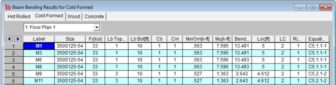
The Label column displays the beam label.
The Size column displays the beam size. When no adequate member could be found from the available shapes, this field will display the text “not designed”. When this occurs, consider re-framing, relaxing the design or deflection requirements (see Design Optimization), or adding more shapes to the available Redesign List (see Appendix A – Redesign Lists).
The Fy column displays the yield strength of the material.
Note:
The Lb top and Lb bottom columns display the unbraced lengths associated with the controlling bending check. See Unbraced Lengths for more information on how these values are calculated.
The Cb and Cm columns display the bending coefficients associated with the controlling bending check. More information on how these values are calculated was presented previously in this chapter.
The Mn/Om or phi*Mn column displays the calculated allowable bending moment capacity based on Section C3 of the applicable AISI code. The Mu column displays the maximum actual bending moment demand that the member experiences. The sign convention is defined so that positive bending will result in tension in the bottom fiber.
The Bending Check column displays the maximum bending check calculated by the program. This check is equal to the actual demand (bending moment) divided by the beam resistance (moment capacity). This bending check is calculated at 100 locations along each beam for each load combination and the maximum demand (moment), the location, and the controlling load combination are reported.
The Location column displays the location along the member where the maximum bending check occurs.
The LC column displays the controlling load combination which resulted in the maximum bending check.
The Equation column displays the code equation that controlled in the calculation of the bending check.
The Column Results Spreadsheet summarizes the code check results and records the design results for columns and may be accessed by selecting Column Results on the Results menu. The spreadsheet has four tabs: Hot Rolled, Cold Formed, Wood, and Concrete.
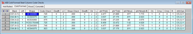
The Stack column displays the column stack label.
The Lift column displays the lift number for the physical column. Lift No. 1 is the lowermost physical column in a stack and the lifts are numbered sequentially moving up the column stack.
The Shape column displays the physical column size. When no adequate member could be found from the available shapes, this field will display the text “not designed”. Consider re-framing, relaxing the design or deflection requirements (see Design Optimization), or adding more shapes to the available Redesign List (see Appendix A – Redesign Lists).
The Code Check column displays the maximum combined axial and bending check calculated by the program. This value is equal to the actual combined axial and bending demand (stress or force) divided by the actually column resistance (allowable stress or ultimate capacity). You can see the details of this value in the subsequent Axial Resistance (Pn/Om or phi*Pn and Tn/Om or phi*Tn) and Flexural Resistance (Mnyy/Om & Mnzz/Om or phi*Mnyy & phi*Mnzz) columns of this spreadsheet. This check is calculated at 100 stations along each physical column for each load combination and the maximum check is reported.
The Shear Check column displays the maximum shear check calculated by the program. This value is equal to the actual shear demand (stress or force) divided by the actual column resistance (allowable stress or ultimate capacity). This check is calculated at 100 stations along each column for each load combination and the maximum check is reported.
The Elev columns display the absolute elevation along the column stack where the maximum code check occurs.
The LC column displays the controlling load combination which produced the maximum code check and/or shear check.
The Dir column displays the column local axis along which the maximum shear check occurs.
The Pn/Om (ASD) or phi*Pn (LRFD) column displays the calculated allowable compressive capacity based on Section C4 of the applicable AISI code.
The Tn/Om (ASD) or phi*Tn (LRFD) column displays the calculated allowable tensile capacity based on Section C2 of the applicable AISI code.
The Mnyy/Om and Mnzz/Om (ASD) or phi*Mnyy and phi*Mnzz (LRFD) columns display the calculated allowable bending moment capacity based on Section C3 of the applicable AISI code.
The AISI Eqn column displays the code equation used in the calculation of the controlling code check.
The Cb, Cmyy, and Cmzz columns display the bending coefficients associated with the controlling bending check. More information on how these values are calculated was presented previously in this chapter.
For all shape types, it is assumed that the transverse load on the member is occurring through the member's shear center. This means secondary torsional moments that may occur if the load is not applied through the shear center are not considered.
Iterations for the effective section modulus (Se and Sc) are ended when a difference less than 1% is achieved in the neutral axis distance calculation with a maximum of 5 iterations. Holes in sections are not considered in the shear strength calculations or for effective width calculations. Deflections are based on the full section properties, not the effective section properties.
Torsional warping effects are not included. Web crippling is not considered.
See the Unbraced lengths for Cold Formed Steel section for the full details.
Kt in Section F2.1 is assumed to be 1.0.
Section C4.4 is not considered in the calculation of the axial strength at this time.
Z Shapes – The bracing length in Lbyy is assumed to brace the minor principal axis. Z sections in compression are assumed to buckle in Euler buckling about their weakest principal axis. The value of rmin is used rather than the geometric rx and ry values.
H Shapes – Hat sections in bending about the y-y axis such that the brims are in compression are assumed braced such that the brims cannot each fail in lateral torsional buckling independently. For AISI S100-12 and older, lateral-torsional buckling is not checked for HU shape.
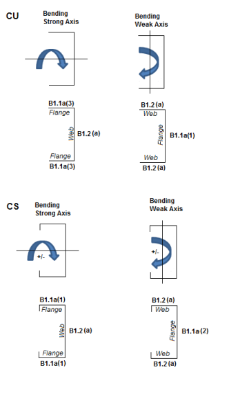
Slenderness Limitations - The w/t limits of Section B4 are enforced. However, the shear lag effects (Section B4.3) are not enforced. Below is an example showing the slenderness checks (AISI S100-12) for a CU and CS shape:
The distance between connector spacing is checked per smax (AISI Eq I1.1-1) however the spacing is considered uniform. The concentrated loads are not checked (AISI Eq I1.1-2) and there is no covered plate sections available (AISI Section I1.3).
The Slenderness ratio is altered based on the intermediate fastener spacing when applicable (AISI Eq I1.2-1). The Detail Report will display the modified KL/r if it governs. This modification is applied if the spacing meets the code limits that states a/ri does not exceed one-half the governing slenderness ratio of the member. The welds length and/or weld/fastener strengths are not checked in RISA (Section I1.2b,c). If the fastener spacing does not satisfy the aforementioned conditions, the global buckling stress of the built-up member is calculated based on the section properties of the individual stud members.
For Back to Back sections, the Weak Axis moments (My) or shear forces (Vz) for back-to-back shapes are not considered in the code check and this is noted in the Detail Report. The program will give you analysis information in the Detail Report and spreadsheets.
For Face to Face sections, the Torsional Constant (J) and Torsional warping constant (Cw) are calculated based on a tube shape if the Connector spacing is set to fully connected (a=0). If the connector spacing is greater than zero (a>0), the J and Cw calculation will be based on the summation of each element.
This message is displayed when the member is not defined with a database shape, or a steel code is not specified on the Model Settings, or no units were specified.
The ratio D/w exceeds the limiting criteria listed in Table B4.1-1 (AISI S100-16) or Section B4.2 (AISI S100-12) for simple lip stiffeners. (“D” and “w” are length of the stiffener and the flat length of the flange as defined in B4.2)
The angle (gamma) for a simple lip stiffener must be greater or equal to 40 degrees or less than or equal to 140 degrees per the criteria in Commentary Section 1.3 (AISI S100-16) or Section B4.2 (AISI S100-12). The angle gamma for this shape is outside this range.
The ratio w/t exceeds the limiting criteria listed in Table B4.1-1 (AISI S100-16) or Section B1.1 (AISI S100-12) for flanges. A value of 60 is used per the AISI code for unstiffened elements and elements stiffened with simple lips.
The ratio h/t exceeds the limiting criteria listed in Table B4.1-1 (AISI S100-16) or Section B1.2 (AISI S100-12) for webs. The program currently considers all webs as unreinforced, so a value of 200 is used as the limit.
The connector spacing "a" exceeds the limiting criteria listed in Section I1.1 (AISI S100-16) or Section D1.1 (AISI S100-12). The "L" in this equation is the beam span (full length of the member).